
What to do when the unexpected happens? Your architecture team provides design documents for building envelope repairs. The contractor begins the field work only to find that the original construction was not completed according to the design documents. Your design and construction team now face a challenge.
The following describes an example of the above-mentioned scenario and how our team resolved the issue.
The Plan

Figure 1 - Existing conditions showing metal strap
The architect provided design and construction administration services for the removal and replacement of existing curtainwall systems and associated components on the 3rd floor of a building that was undergoing interior renovations. This 3-story building consisted of an exterior brick masonry veneer wall with precast concrete banding at the sill and head of the aluminum framed curtainwall assemblies at the 3rd floor. The plan was to replace the existing curtainwall systems, while completing repairs at curtainwall perimeters where they meet abutting substrates including new sheet metal and membrane flashings at the sill, jambs, and head of the curtainwalls. Repairs also consisted of new sheet metal and membrane flashings at prefabricated metal column wraps between sections of the new curtainwalls, as well as new mineral coatings applied to the precast concrete.
The Issue

Figure 2 - Original detail
During the removal of the existing curtainwall system at the first in-place mockup bay, the contractor discovered that the existing precast panels at the sill of the 3rd floor were horizontally attached to the existing curtainwall curb with a metal strap – see Figure 1. Per the original as-builts, and the contract drawings, the precast was detailed to be anchored to the slab/pour stop, approximately 6” below the slab edge – see Figure 2. The general contractor, window and glass specialty contractor, and architect were on site to observe the condition. The team was unsure if the discovered metal clips would support the precast laterally. Review of the void between the precast panels and slab edge revealed that there appeared to be no anchor as detailed in the drawings. The number of fasteners and straps varied at each section of precast, and the metal straps also showed visible signs of deterioration. The anchors were removed to replace the deteriorated curb to which the new curtain wall would be attached.
To carry out the remainder of the curtainwall buildout, the architect was tasked with providing an engineered detail to provide sufficient support of the existing precast panels as well as a curb detail to reflect the addition of precast anchors, and any firestopping measures, if applicable. A quick turnaround was crucial to maintaining the project schedule.
The Solution
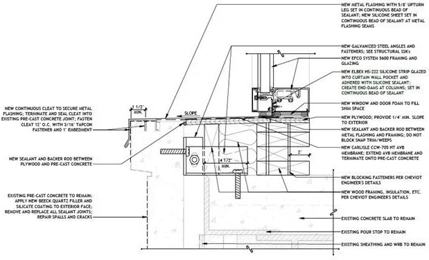
Figure 3 - New detail

Figure 4 - New anchor installed
To develop a solution, the architect worked closely with a structural engineer to modify the sill detail to better secure the existing precast concrete – see Figure 3. A new securement consisting of steel angles and fasteners was developed to attach the precast units to the floor slab while allowing the precast units to remain in place; the precast units needed to remain in place based on the scope of work extents and project budget. The detail also required the removal of the existing sill materials as they were found to be deteriorated. In order to remove the existing deteriorated sill materials, the installation of the new securement had to be performed in intervals so a proper connection could be established between the precast units and the floor slab before complete removal of the sill materials. During implementation of the new detail, it was discovered that the distance between the backside of the precast and the floor slab edge varied. This required careful measurement and multiple new angle sizes, as each location differed. Given the limited access to the cavity behind the precast and area below the slab, the waterproof integrity of those inaccessible areas relied on the sound and intact conditions of the existing components to remain. This made detailing and ensuring the flashing components were properly installed above critical. Ultimately, the detail and installation of the new anchoring was successful with minimal to no impact on the overall schedule and budget of the project – see Figure 4.
GRLA’s Building Envelope Sciences team can help you with your building envelope challenges and work with you to prevent future building complications. Contact us to see how we can help you.